cam and tappet experiment
625 Examples in SimDesign. TEHL camtappet-contact of the valve train.

Testing Of Cam Roller Follower Systems About Tribology
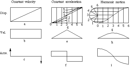
To compare the throw profile of two types of cams simple harmonic parabolic cam and tangent cam with two types of followers flat follower and dome follower.

. Therefore tribological cambucket tappet component Stribeck tests were used to determine the friction behavior of ultrashort pulse laser fabricated microtextures and PVDPECVD deposited. Equipment Description Of Experimental Apparatus Cam and tappet device is used to measure and analyse the effect of various followers and tappet motions on different types of cam. The various test procedures employed in the experimental program are shown in Table 2.
Attention to the front and rear view position of the cam as the cam guiding rod bore hole. A mechanical constraint cam also be introduced by employing a dual or conjugate cam in arrangement similar to what shown in Figure 6-7. Firstly the changes of friction with valve spring load camshaft revolution speed and oil temperature are examined for current materials and CD-level oil of diesel engines.
Sophisticated instrumentation has been used to measure the velocities and synchronize them with the lift event. Six different types of cam and lifter combinations were used. The apparatus used is the cam and tappet apparatus with roller domed and flat followers equipped with dial indicator.
The experimental results showed high sliding during contact with the cam base circle up to 20. Figure 6-7 Dual cam. Machine design and cad lab experiment no.
Each cam has its own roller but the rollers are mounted on the same reciprocating or oscillating follower. Made available by US. Loosen the fixing screw 23 with the provided Allan key and insert the flat tappet followeApply a thin film of grease to the flat tappet.
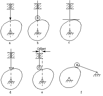
The purpose of this experiment is to investigate tappet motion for several different cam profiles and the effect of using different followers. Tappetbore friction and torque at the camshaft were measured for a direct acting bucket tappet using a camtappet friction apparatus. - Investigate tappet motion for several different cam profiles and to see the effect of different followers.
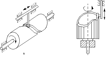
A follower is used to transfer the motion to the required machine part. The Follower rotates in an oscillating or circular arc. Data Observation and Results.
Cam and Tappet by Af idiahaisyah Salleh Submission date. The contact force model for. View Experiment 3 _ Cam and Tappetpdf from MECHANICAL MEMB331 at Tenaga National University Kajang.
Equation of the cam-tappet friction pair was established. Department of Energy Office of Scientific and Technical Information. The mechanism for Cam and the mechanism for Follower depend.
Universiti Tenaga Nasional 2006 Mechanical Design and CAD Laboratory CAM AND TAPPET EXPERIMENT OBJECTIVE The objective of the experiment is to investigate tappet motion for several different cam profiles and to study the effect of different followers. Statement of Purpose Objective. To compare the velocity profile of two cams simple harmonic parabolic cam and tangent cam 3.
In the present study the frictional force between the cam and tappet is directly measured using a load sensor installed in a test rig and the following is carried out. Day and Date experiment performed. The engine vibration and noise induced by a valve train element are analyzed through the modeling and experiment method.
Data For Convex cam. The load history of the cam-tappet contact stress. CAM AND TAPPET EXPERIMENT Objectives The objectives of this experiment are.
View cad lab 3 cam tappetdocx from aa 1universiti tenaga nasional college of engineering department of mechanical engineering memb 331. The preview shows page 2 - 4 out of 9 pages. The results showed that for the particular geometry tested tappetbore.
Tappet cam and wipers are names given indiscriminately to those irregular pieces of mechanism to which a rotary motion is given for the purpose of producing by sliding contact. Cam A sliding or rotating of mechanical device used for transformation of rotary motion into oscillatory motion or vice versa t o a second body which is called as follower which in contact. The two knurled nuts were undo and the two washers were removed.
A cam and tappet mechanism comprising a straight reciprocating rod a compression spring on the rod for projecting it a-tappetlever hinged at one end and having an aperture near its opposite end through which the rod freely passes a nut on the upper or outer end of the rod a strong spring engaging the inner side of the tappet lever and holding it firmly against the nut. For the most part the test methods were based on procedures followed by the engine builders for studying cam and lifter materials and design. The relative sliding of tappet roller to cam has been experimentally determined by means of a simulator rig.
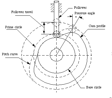
The objective of the experiment is to investigate tappet motion for several cam profiles and to see the effect of different followers. Then the contact stress between the cam and the tappet was simulated by using the multi-body dynamics simulation software ADAMS respectively for the engine running at idling speed rated speed and over-speed condition. The laboratory test installations are very simple since.
Tappets are generally used for heald shedding. Rotating Cam Translating Follower. A tappet is a cam having some dwell period which controls the updown movement of heald shafts and the time of opening of the shed.
Any sudden movement to the dial indicator stem was avoided. The objective of the experiment is to. Follower inhibits the push and pulls of the Cam.
SRemove the knurled nut 24 and mount the circular cam 1 as shown in figure 11. Experimental evaluation of tappetbore and camtappet friction for a direct acting bucket tappet valvetrain. Tappetbore and camtappet friction torque and friction coefficient as a function of cam angle were derived from those measurements.
A follower is a mechanical component concerning which the Cam rotates in an oscillatory or circular motion. Situated on the rear of the cam. THEORY Introduction Cams are widely used in engine machine.

Cam Follower Mechanism Mechanical Kinematics Engineering Cam Gtu Youtube

The Motored Single Cam Rig A Photograph Of The Rig B 2d Schematic Download Scientific Diagram

Testing Of Cam Roller Follower Systems About Tribology

Testing Of Cam Roller Follower Systems About Tribology

Solved 1 Lab Mechanics Of Machines Me 343 Study Of Cam Chegg Com
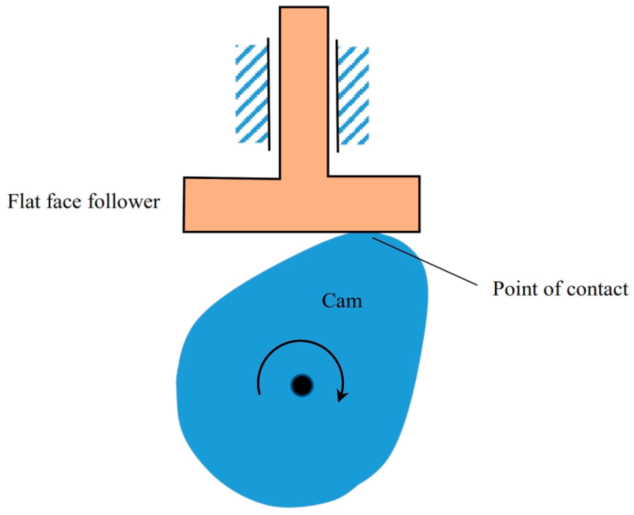
Lubricants Free Full Text Lubrication Analyses Of Cam And Flat Faced Follower Html

Beat Up Mechanism In Weaving Weaving Shuttle Loom Motion

Loom Timing Diagram Basic Concepts Loom Engineering Colleges

Schematic Of Cam Mechanisms With Flat A A Centrally Located Download Scientific Diagram
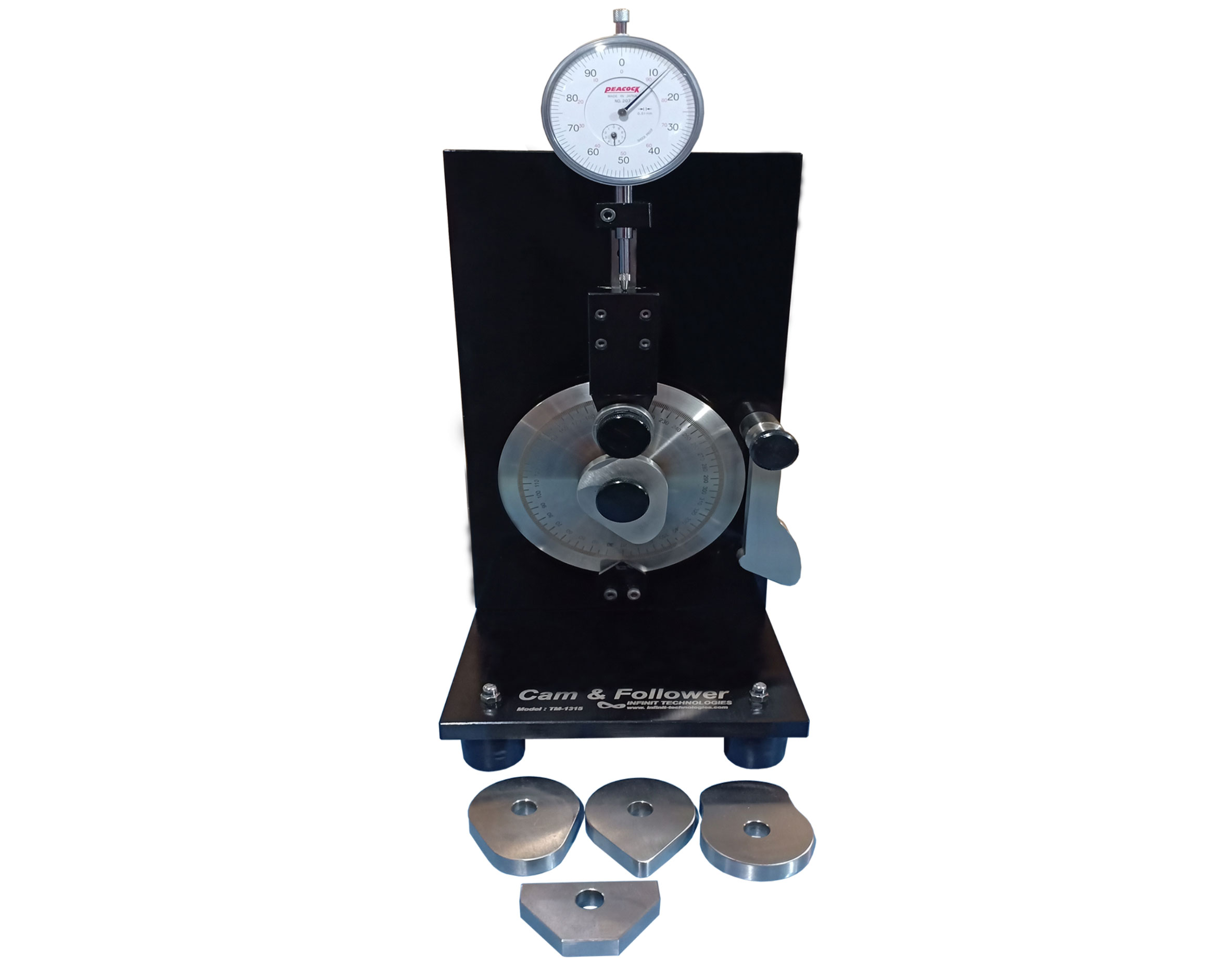
Tm 1315 Cam And Follower Apparatus Infinit Tech

Schematic Of A Cam Tappet Contact Configuration Download Scientific Diagram

How To Choose The Best Cam Lifters For A Gen Iv Ls Engine Ls Engine Diy

Cone Under Picking Mechanism Flow Chart Chart Cone
